Heathkit IM-1202 Digital Multimeter
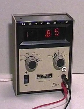
This Multimeter has been build from a kit by Heathkit,
somewhere around 1972.
After some work, it functions again. But it is not a very precise instrument.
I bought this really nice meter on the quarterly NVHR radio flea market. The original instruction booklet came with it, containing detailed assembly instructions, the schematic diagrams and callibration procedures. By the way, scans of the schematics are also available on a few sites on the Net: at the Heathkit site of The Circuit Archive ( page 1, page 2, page 3) and maybe on the BAMA boat anchors site, too.
It is mains powered and consumes about 8 W. The logic circuitry is TTL (transistor-transistor logic). The Display range is 0-199 and the maximum error should be a few counts plus 1%.Its ranges are:
Some extra analogue circuitry is present to convert AC into DC for the AC ranges and there is a constant current source for the resistance ranges. It's a pity they didn't add a DC pre-amplifier for the current ranges for there is a voltage drop of 2 V when measuring current, at full range, which is too much in many circumstances.
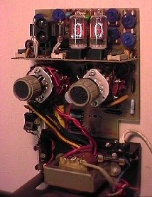
A look a the inside. The boards have been
turned 90 degrees backward. On the
bottom you see the mains transformer still
attached to the case.
This IM-1202 appeared to be in good condition, but did not work properly. The nixies showed all the digits simultaneously. Manipulating the boards made this go away and display "00", but the blurred digits came back every now and then. A few loose contacts, apparently. After I had taken the boards out of the case, the digits sometimes went black when I touched the logic board. I found a loose soldering joint in the neon supply voltage and fixed it. After this I made sure that the connections between the logic board and main board were OK, I got a solid and constant display of "00".
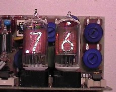
A close look at the two ZM1000 display tubes.
The left one is the original, brand X.
For this
picture, I swapped the one on the right and
inserted a Philips ZM1000.
You can see that
the top of the Philips tube is darker by
virtue
of an internal screen blocking the light
coming
in from above. Further, the Philips tube had
a nicer color.
The digits were evenly orange
while the brand X tube
had a slight purple tinge.
I measured some voltages and I found that the outputs from the A/D converter that drive the logic circuit that start and stop the counter cycle, were actually out of range for TTL circuits. I took a closer look at it and found that the Zero Adjust control (potmeter R152) would have some influence on these levels. I turned the pot and suddenly the display came to life! Now as far as I understand the circuit, this pot does something to balance the two non-TTL voltage levels to the logic. So this means the operation of the A/D converter is influenced by the temperature of the logic circuit these signals are going to. Now the two signals go to the same chip and they have done their best to make it symmetrical, and the flipflop circuit will cancel oscillation tendencies of TTL inputs that are driven between their 0 and 1 level, so it does work. Still, to see TTL circuits being used this way causes me a definite feeling of nausea.
After this, I was able to set and callibrate the meter. I had a useable nixie multimeter, but a lot less accurate than my usual DVM. But it makes a nice museum piece. A pity that the handle on the top is missing.
Copyright © 2002 by Onno's E-page published 2002-04-01, last updated 2008-08-22