Home built universal Frequency Counter
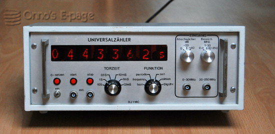
This 7-digit counter built by a German radio ham is a nice basic
TTL based frequency counter.
It has 7 ZM1000 nixies and one ZM1002 to indicate units.
The counter can measure frequency and time and can handle up to 250 MHz. Two knobs on the front are used to set gate time and select one of 6 functions:
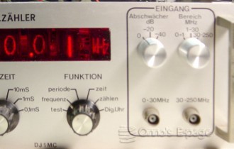
A view of the controls for range, function and input selection.
Most of the circuitry is mounted on a single large circuit board. This board has been made by the constructor of the counter, as it is bearing his call-sign. Looking at the quality of the board (it has tin-plated traces), I get deep respect for his skills. Electroplating a PCB, probably using the tin coating to protect the copper not to be etched away is a sophisticated way of PCB manufacturing.
This counter has a lovely nixie tube display consisting of:
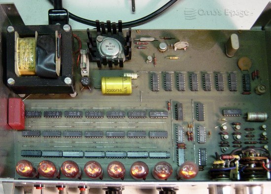
A look inside from above, showing the ciruit board and it contents.
The control circuit consists of 2 SN74121 monoflops, a 74S00, a 7400, a 7451 and a 7413. The counter has a 1 MHz crystal as frequency reference and a series of 7 SN7490 dividers to produce the different port times and timing frequencies.
For the 250 MHz input, a fast counter chip is used as a pre-scaler. This is probably an ECL chip, as it has a heat sink on top. It is placed on a separate pre-scaler board situated right behind the 250 MHz input below the main board.
Under the main board there is an additional PCB that holds 5 extra 7400 chips as reset circuitry for the clock function.
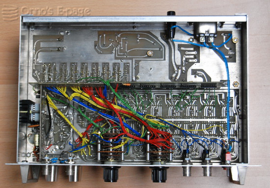
A look under the board, showing the auxiliary boards, inputs, range switches and wiring.
The power supply is using a small (25 VA) transformer, that looks like it has been custom wound. The label states it can deliver 8.5 V at 1.5A and 170 V at 50 mA. The constructor has added an extra 15 turns of wire to boost the 8.5 V secondary. The +5V is regulated by an LM305 buffered by a 2N3055 and 2N2807. The power transistor is running quite hot as does the transformer. I think the power supply may be a bit underdimensioned.
After I checked the state of the components, I switched on the counter. It just worked and showed a series of pretty zeroes. When I tried the Clock mode, that just worked. Setting the time requires some fiddling with the period selector and the start/stop buttons. I will have to recallibrate the time base and see if I can find a purpose for this neatly built DIY counter that deserves to be kept in honour.
Copyright © 2012 by Onno's E-page published 2012-08-04, last updated 2013-01-16