FC7008 Frequency counter
I read about this design in the ELV magazine in 1999.
I liked it a lot so I ordered the kit and built it.
Though this was my first experience with SMD components, all went well
and the counter worked fine. At first, that is.
In order to callibrate the instrument I had to come up with some tricks.
Callibration succeded and I'm quite satisfied with the counter now.
This is a microcontroller-driven frequency counter,
like many of the frequency counters you find today.
Using a microcontroller gives a lot of flexibility for different
operating modes, and it gives you the opportunity to calculate
frequency from time and vice versa. This results in much more
precise readings with a moderate gate time.
And of course, a microcontroller-based design uses much less
components. I know because I built a TTL-based frequency counter in
1980. That one had lot of boards and the controller board that
generated the gating signals and selected between period/time and
frequency, was rather complex.
The FC7008 can measure up to 80 MHz on its standard input.
There is also a divide-by-100 prescaler that goes up to 1.3 GHz.
It has 8 digit multiplexed display.
Push-button switches are used to select operating mode and gate
time.
Inside is a 25 MHz "OXCO"
(temperature-controlled crystal oscillator or "crystal oven").
This should give the device a precision of a few ppm.
That is, if you have facilities to callibrate the device...
There is also a cheaper version, the FC7007, with only seven
digits, no OCXO and no prescaler.
Now of course, to build a kit is much less impressive than to design
it yourself. But to design a frequency counter is a lot of work.
Anyway, to build this one was a nice experience, yielding results
quickly.
The kit is well designed and everything was complete.
This also meant things went fast. The assembly was finished in a
few nights.
There were a lot of SMDs in the circuit. For me this was my first
experience with SMD components as an amateur. But it went well.
I used a very thin point (0.8 mm) for my soldering iron, and thin
solder wire.
Positioning a component with a pair of tweezers,
you can make one of the ends stick to one of the solder pads.
then solder the other end and resolder the first end using just
enough solder. This procedure is much slower than what I you can do
with normal wired components, but it works.
The counter did not work immediately.
I had forgotten some of the connections between the two circuit
boards. A washer under one of the screws that fix the front board
to the main board caused a short circuit because it touched a
trace on the front circuit board.
This could easily be corrected by shifting the washer a bit.
I would consider this a design flaw, the hole should not have
been so close to the trace.

Fixing oscillator trouble
This counter contains a temperature-controlled reference
oscillator (OCXO).
This is actually a separate kit, that is included with the FC 7008 kit.
I built it and tested it.
Although the output
voltage was less than specified, it was within the range TTL
circuits need so I did not give this much consideration.
After two months, the counter did not work any more. It was able to
count events but not frequency or period.
The "measuring" LED was almost constantly on indicating
that the measurement cycle was somehow disturbed.
I opened up the cabinet and started searching signals with a scope.
After analysing the circuits I came to the conclusion that the
input circuit wasn't triggered properly. Then I found out that the
reference signal wasn't there. The OCXO didn't work.
I made a quick and dirty fix by connecting the output of the 16 MHz clock
oscillator to the "external reference" input.
Now at startup the counter said "ref ext - 16 MHz", which is quite
correct from its point of view, and measured frequency again.
Of course, the clock was not callibrated, but for the moment that
was not an issue.
I opened the oscillator and poked my scope's probes in it (opening
it was not easy, the guys at ELV have not designed this crystal
oven to be serviced).
It seemed that the Collpits oscillator was dead.
Touching one of the crystal leads started it, however.
Apparently the oscillator was marginal.
I played a bit with the capacitors in the divider in the crystal
circuit and got it back to work again. Apparently, the capacitors
did not fit the crystal very well.
As I said, something was wrong with the output voltage.
I checked the output buffer and found out that the signal went all
up against the positive supply rail, but not to ground. Apparently
the output transistor was not biased properly.
After some quick calculations I decided that the output circuit's
bias was very sensitive to component variations.
I changed the bias and got a satisfactory 4 Vtt output.
Callibration without reference equipment
Now I had repaired it, I wondered what use the crystal oven was if
I couldn't callibrate it.
I remembered that the carrier of some radio stations is kept very
precise by coupling it to an atomic clock.
In 1973, Radio Bulletin described a callibration procedure that used
the Droitwich LW station on 200 kHz as a reference.
They tapped a 100 kHz signal derived from the oscillator to be callibrated,
and coupled it loosely to the ferrite antenne of a portable radio
tuned to Droitwich on 200 kHz.
The interference of the two signals caused a beat frequency equal to the
frequency difference. They tuned the oscillator so that the beat frequency was
as low as possible. I once used this procedure and it worked.
Looking for "Droitwich" and "frequency reference",
I found a page "Using BBC transmissions as a frequency reference"
on the BBC web site.
Fortunately, I made a printout of it, because the page seems
to have disappeared since.
It told me that Droitwich was on 198 kHz now,
which is a bit of an awkward frequency if you want to use
the Radio Bulletin interference method.
Just to use the signal from a radio station as the input for
the frequency counter didn't seem practical because the signal is too weak
to use as an input for the counter and because noise will disturb
your measurements.
You'd have to build a small-bandwidth tuned RF amplifier to do this,
maybe a PLL to replicate the reference signal without noise.
This can be done, but it's a lot of work.
And as BBC indicated, the short-term precision of a received
radio station frequency is not so good because of phase differences
due to atmospheric conditions.
The good news was that BBC has other precision signals.
On their TV broadcasts they keep the color subcarrier signal
within 1 Hz of the specified value of 4.43361875 MHz.
Now this is a signal you can easily recover from any color TV.
In a color TV there is a local crystal oscillator that is kept in phase
with the color reference signal at the broadcast station.
So I thought, because the local oscillator is kept in phase with
the reference signal, it must almost have the same +/-1 Hz precision.
Now this may not be completely true. The TV broadcast signal may
suffer quite large phase shifts that remain invisible because the
color subcarrier and the reference signal will suffer the same
amount of phase shift. As long as the local oscillator in your
TV can follow the phase shifts, the image is good.
But as long as the phase shift is constant, the frequency is too.
Maybe someone someday will provide me with a thorough error analysis so
we will know exactly what the precision of the received signal is.
I did not give this much thought and assumed the signal path from
London to my house was good enough to let me get away with it.
So I decided to callibrate the counter using the color reference signal
tapped from a portable TV when tuned in to BBC.
Finding the 4.43 MHz crystal in the TV was easy. Although all the
circuitry for color demodulation was around a single IC, it was
easy to see what the output of the oscillator was by analysing the
circuitry around the crystal. I connected a 10:1 probe to it that
went to the input of the counter.
Now don't try this at home if you don't know what you are
doing. You may severely damage your TV set and your health,
too, if you don't know what parts of the inside have dangerous
voltages.
The OXCO has two adjustment controls:
one coarse, this is a trimming capacitor on the inside,
and one fine, this is an external control voltage for a varicap
diode parallel to the trimming cap. There is a multiturn pot on the main
board to set the control voltage.
The fine adjustment has a span of less than 100 Hz so you can't
afford not to set the trimming cap first.
Unfortunately, you have to take the OXCO apart to reach the trimming cap,
you cannot set it in-circuit but have to do that on your bench.
First, I added a trimmer capacitor to the clock oscillator to
be able to callibrate it.
I trimmed it to get a reading of 4.433619 MHz.
Then I used the now callibrated counter to adjust the OXCO to
25.000 000 MHz on my workbench. It was now as precise as
the clock oscillator was.
After setting the trimming cap, I sealed the oscillator and
soldered it in place.
I let the counter and OXCO warm up for half an hour.
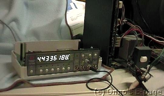
Then I connected the counter to the TV and adjusted the fine
control to get a reading of 4.4336188 MHz.
The counter had to be set to 10 s gate time to get a reading with
a resolution of 0.1 Hz like this.
End of callibration, no expensive reference equipment used!
I made the photograph at the top of this page to prove all this.
Switching my TV between channels, I noticed that most other
stations were also quite precise.
The stations that were off more than 10 Hz were commercial TV
stations.
Is this because a precision subcarrier does not pay, or
do they get suffer from relativistic effects that change the flow
of time when the signals are travelling the way to and from
their broadcast satellites?
Still later, when I was aligning the
UM58 regenerative receiver,
I accidentally found another way to align a frequency counter to
broadcast transmissions.
Normally, the signal from a broadcast station is too weak to be
used as an input to a frequency counter.
But when you set the feedback control of a regenerative receiver
so that it just oscillates, you can use the receiver as a powerful
amplifier and filter.
When the receiver is oscillating, you hear a note.
This is the beat frequency, the difference between the broadcast signal
and the receiver's oscillating detector stage.
As you tune in to the station, the tone will become lower as you approach the
real frequency of the broadcast station.
Suddenly, the tone disappears when the detector locks in with the station.
I noted that in this stage, the readout of a frequency counter hooked
up to the detector output is very stable.
So you are looking at the broadcast station's frequency, the signal being
amplified by the oscillating detector stage,
locked to the broadcast station.
After all this trouble, I mean fun,
the counter has proved to be a useful and easy to use instrument.