AT Super 660 WK3 radio (1951)
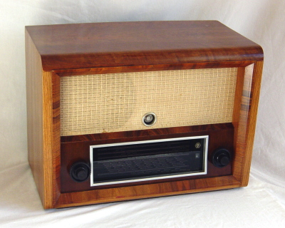
The AT Super 660 is an East-German radio from the early fifties.
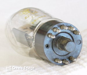
I bought it because of the typically German valves with
"G8A" base.
The radio is a mix of craftsmanship and old design, with a few
odd design features.
I was able to make it play well again and have restored
the case to make look good again.
The AT660 has a reasonably large speaker and delivers a good sound.
It has 5 frequency ranges: LW, MW and 3 SW ranges.
On the dial, both frequency and wavelength are indicated.
Most Western European radios of the time indicated only wavelength.
The radio is built as an average superheterodyne using the following
set of valves, all made by RFT (East German valve manufacturer).
- ECH11 frequency changer
- EBF11 IF amplifier and detector
- EF11 as AF pre-amplifier
- EL11 as output amplifier
- EM11 tuning indicator
- AZ11 rectifier
All valves have a “G8A” base which is why I bought this radio.
These are practically only seen in German radios.
The “G8A” is a base which enforces a correct insertion in the
socket, helps to find the right orientation in dark places and holds the
valve tightly in place.
It can be seen as an improvement of the Octal base.
A base that has advantages, but is expensive.
After WW-2 better valve bases were developed that cheaper to produce.
So I found it quite odd to see a radio from 1951 that uses G8A valves all over.
I bought this radio from a friend.
The case looked nice and stylish, but a bit scratched and a few
small pieces of veneer had come off.
My friend told me the rectifier had a broken heater, so I thought
it would be an easy repair.
After I replaced the rectifier and switched the radio on, I noticed some
sparks in the new rectifier.
I switched off immediately and tested the electrolytics.
These had almost entirely lost their capacitance and had a
considerable leakage current.
These electrolytics are encased in oiled paper cylinders, sealed at
both ends with pitch.
The pitch was cracked and some white powder was leaking through
the cracks.
Because the old electrolytics were so large,
it was easy to fit new capacitors in.
I used 450V types because the originals were 450 V too.
I thought this was overdone, but later on I found out it wasn't.
After replacing the electrolytics, I tried the radio. No sound at all.
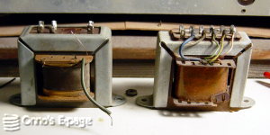
When I checked the output transformer, it turned out to have an interrupted
primary winding.
I looked at the schematic and saw a possible explanation: the terminals for
an external loudspeaker on this radio are connected to the primary of the
output transformer, not to the secondary.
This means things go wrong if you connect a low-impedance speaker
or accidentally short one of the loudspeaker terminals to ground.
I found a suitable replacement transformer, though I was not sure of the impedance.
It turned out to work, but the sound was distorted and the
supply voltage was low.
After 5 minutes, one of the HF filter capacitors across the HV winding
overheated and started sizzling. I turned quickly off the radio and hoped
the power transformer would not be damaged.
For the moment I decided to do without the HF filter capacitors
and tried the radio without them.
I measured the current through the output valve, which was about 100&nsp;mA.
This meant he vale had ample emission, which is good,
and the coupling capacitor from the AF pre-amplifier was leaky,
which is bad.
I measured only 2 MΩ resistance.
I checked a number of other capacitors, and these were very leaky, too.
Actually, testing with my HV power supply set to 250 V, the total
of the leakage currents was 3 mA.
So I decided to replace most of the paper capacitors.
Fortunately, these RFT capacitors are relatively easy to fix invisibly:
they are encased in a glass tube, sealed with pitch.
I heated the pitch with a soldering iron,
pull the old capacitor out and fit a polyesther capacitor in.
Because all of the paper capacitors were 500 V types, I used
500 or 630 V polyesther capacitors.
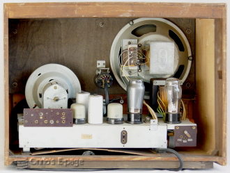
The loudspeaker is a type with a field coil instead of a permanent magnet.
This field coil is also used as the power supply choke.
I temporarily replaced the choke with a spare choke to be able to
test the chassis outside the case without having the
the clumsy loudspeaker and baffle on my workbench.
When I turned on the radio I was surprised to see the supply voltage rise
to a staggering 480 V, to drop to 320 V
after warming up, which was still quite high.
I realised this was not the intended plate voltage,
the loudspeaker would cause a 100 V voltage drop
because its field coil has a resistance of 1500 Ω.
That is much more than the resistance of the choke I was using.
Now I understood why all the capacitors had such a high voltage rating!
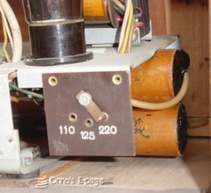
The power transformer delivers a higher voltage to compensate for
the voltage drop across the loudspeaker's field coil.
All the capacitors must be able to withstand the 20 second voltage surge
at startup, that's why they are 450V and 500V types.
The radio was playing again, though not very impressively.
Om MW, I received a few stations in the 500 kHz range, and
hardly any at higher frequencies.
I decided to realign the coils.
In that process I found out another defect: the 4 trimming capacitors that
are used to align the MW and SW frequency ranges, had lost their capacity.
These are silver plated ceramic capacitors.
The connection between the silver plating and the
connecion lug seemed to be interrupted.
This explained why reception on the high end of the MW band was so weak.
I was able to fix the two trimmers on SW by using conductive paint.
The two trimmers on MW could not be fixed.
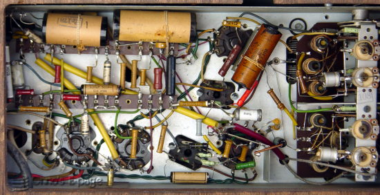
I added two air trimmers (they can be seen on the photograph of the
underside view).
After this, the radio played very well again on MW and resonably on SW.
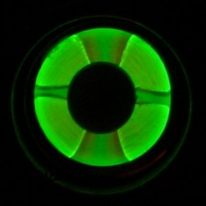
The general condition of the valves is quite good actually, as can be seen
on the photograph of the EM11 tuning indicator, which is still very bright.