Erres KY515 radio (1952)
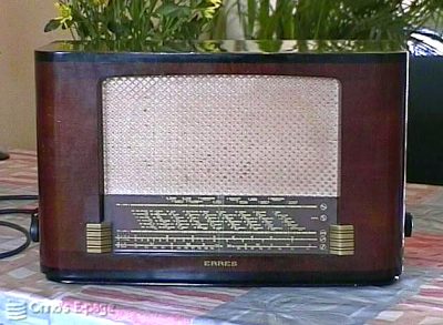
The Erres KY515 is a table top radio from 1951,
a straightforward superhet using Rimlock valves.
This is a rather ordinary radio from the early fifties. It has 3 wave bands: MW, LW and a single SW band. It uses Rimlock ('40-series) valves: ECH42 for frequency changer, EAF42 as IF, EBC41 for detection and first AF, EL41 as AF end stage. And there is an AZ41 rectifier. The case is veneered plywood, painted shiny black on the top. The tuning scale does not look too good. It has either been a very cheap silkscreen job or the paint has become powdery by oxidation, making the lettering hazy.
I bought this one in spring 2001 on a flea-market. It reminded me of an old radio we used to have in the kitchen when I was a boy. We always listened to it during lunch. That was one of the first radios to ..err.. teach me what radios looked like inside. This KY515 resembles our old radio, although it is not identical.
The person selling it told me the radio worked but that the scale illumination was faulty. He told me I needed 18 V lamps. That seemed a bit odd, usually 6.3 V lamps are used inside this kind of radio, working from the heater winding of the power transformer.
The radio really needed some dusting inside. The thick layer of dust showed that the tuning capacitor had been in a half open position for years, so the radio can't have been used the last 10 years or so.
First I let the electrolytics reform on my workbench HV supply for two evenings. Then I tried the radio. Nothing happened. No scale illumination. No mains voltage appearing on the mains switch. The rubber mains cord turned out to be interrupted near the plug. After fixing this, the scale illumination worked. Nothing wrong there (and no 18 V bulbs, by the way). I got some sound. Some whistling at the turn of the tuning knob, some cracking, but no recognisable voices or music.
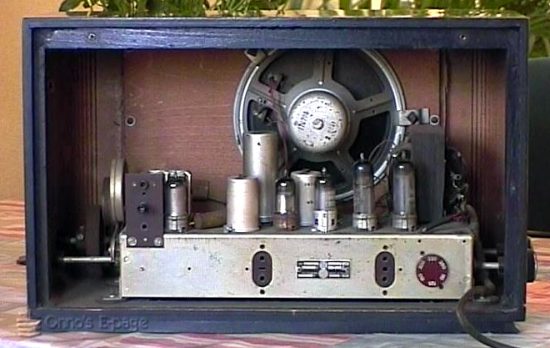
A view on the inside, from the back.
Besides being very insensitive, it had some kind of low-frequency oscillation, a repeating popping sound. The output valve was in poor condition: it only drew 20 mA. But in the "Phono" position, the output amplifier worked reasonably. The low-frequency oscillation remained, although fainter. I tried pulling the IF amplifier valve (power off, of course) and switched on again. Now the popping had gone. Putting back the IF valve, my scope showed that it was oscillating at the IF frequency. The oscillation stopped regularly, which caused a varying DC voltage at the output of the detector, which explained the popping sound. Whenever I clipped my scope probe to the anode of the IF, the oscillation stopped because of the extra damping. Even with the probe connected, I had reception now.
Exchanging some bypass capacitors did not help. But when I measured the supply voltage, the low-frequency oscillation changed a bit. I put an extra 0.1 μF capacitor in parallel to the smoothing capacitor, an electrolytic capacitor. This cured the oscillation. Probably the electrolytic had dried out a bit, causing lower capacity and worse HF characteristics.
Some time later the radio developed a strong hum. I checked the supply voltage and found out that there was a hum of about 4 Vtt on the second bypass capacitor and on the buffer capacitor. This hinted at a bad electrolytic again. Checking it, I found out that it had entirely lost its capacitance. I put an electrolytic in parallel with it, and now the hum has gone and the the radio is playing fine again.
Copyright © 2001 - 2008 by Onno's E-page published 2001-05-03, last updated 2003-07-06