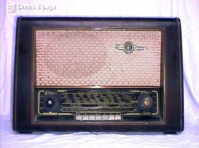
Nordmende Fidelio 53
This Nordmende radio is an interesting well-built radio.
It has a rather moderm FM tuner and an electrostatic tweeter
to realise a sufficiently broad audio spectrum for FM reception.
This Nordmende radio is dating from 1953, according to a stamp on the bottom. It is an early FM radio and must have been quite advanced for its time. On a German web site by Christof Neudecker, I was able to identify it as Fidelio 53. Apparently, Nordmende has produced several Fidelio models, where "Fidelio" suggests "hi-fi". The sound is really good indeed. For the high frequencies an electrostatic tweeter has been used. Later on, in the Fidelio 56 model, Nordmende returned to conventional magnetodynamic tweeters.
On the front, there are 7 push-buttons and 2 sets of turning knobs. The knobs on the left are volume, treble and bandwidth control. The knobs on the right are bass control, orientation of the ferroceptor antenna inside and tuning. The 7 pushbuttons are: FM, SW, MW, LW, pick-up, internal/external antenna and "AUS" (off). On the back, there are inputs for FM and AM antennae, 2 loudspeaker outputs (high and low impedance), and a pick-up input.
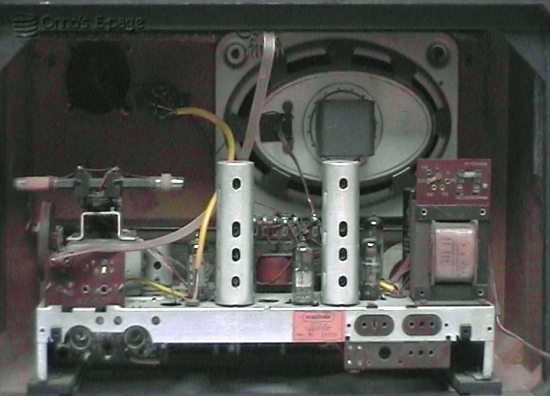
Nordmende Fidelio 53 seen from the back.
I got this radio from a friend. It looked a bit dirty and the knobs on the left were missing. When I opened the back, I saw there was some rust on the chassis and the transformer. Overall though, on the inside it looked reasonably good.
At first I could not find a schematic for this model, so I started with a schematic of the Fidelio 56 instead. The valve line-up of that model is about the same, except for the FM tuner. And the Fidelio 56 has 3 speakers instead of 2. But my '53 had so many faults I needed the real schematic. I didn't know how to connect the tweeter connections, the FM tuner used different valves and I wasn't sure about the waveband selector. Fortunately, Herr Neudecker was so friendly to send me a scan of the schematic. But I had to start without.
First, I started to reform the HV electrolytics and test a number of capacitors. The coupling capacitor to the output valve was very leaky, as was the bypass capacitor on the AF preamp. Replacing these capacitors gave me enough confidence to power up the radio. No sound at all.
Second, it turned out that the loudspeaker connections had been cut, and the speaker wires had been wrapped loosely around the connection lugs on the output transformer. The wires were heavily corroded, so there was no contact. I resoldered the main speaker, but left the tweeter unconnected for the time being. The ohmmeter said it was interrupted. I thought it might be an electrostatic speaker, in which case it had to be connected to the primary of the output transformer. Not knowing what to do, I decided to leave it for the moment. Later on, when I had the schematic, I was able to fix this. After I reconnected the speaker, I got some sound from the AF section. All AM bands were silent, though. The FM band worked, but only in a part of the band. There was no reception below 97 MHz or so.
Third, I checked the AM section. Injecting modulated IF signal gave some output signal, though a bit weak. So the IF stage and the mixer worked. schematic.My scope told me the oscillator did nothing. I checked the circuits on the bandswitch. It turned out that there was a short to ground. I partly dismantled the switch to find out why. The trimcap for the MW range seemed shorted. But after I bent the connections a bit, it was ok again. Odd.
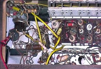
Look at components under chassis.
Then I tried the radio. AF amplification was better now. The noise on FM was louder. I could get a few stations on AM, but only at wide open volume control. When I touched a wire in the IF with the earth lead of my scope, suddenly there was a lot of noise, to disappear again after I removed the scope. I tried this some times, but could not find why this was. I checked and replaced the cathode bypass capacitor in the IF stage. It was a paper cap gone bad, but this made no difference. Suddenly I got an idea and tried the bandwidth switch. Now the radio worked! I turned down the volume and could get a lot of stations on MW. LW and SW. But in the other position of the bandwidth switch, no reception.
Sixth, I unsoldered the wires to the switch and checked. Indeed, one of the contacts had a high resistance. I decided to clean it with contact spray and tried the result. Perfect reception on AM!
Seventh, I had to tackle the FM. It was hard to measure the oscillator output. I just replaced the second EC92 and Bingo! After that, some cracking remained that disappeared after cleaning the tuner.
Eighth, time for the Magic Eye. During all this I had noticed that the EM34 tuning indicator did not work at all. This turned out to be a very common fault: the two 1 MΩ resistors on the EM34's socket had become interrupted. Replacing them made the magic eye work fine again.
After all this trouble... no, it was fun, I traded this radio for the magnificent Monroe 640 calculator you see in the Neon Nostalgia section.
Copyright © 2002 by Onno's E-page published 2002-09-15