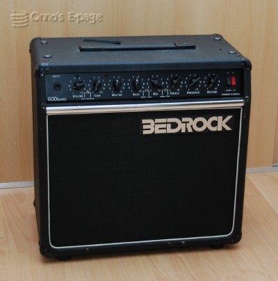
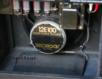
This Bedrock 600 guitar combo belongs to a friend of mine.
He told he it had broken down and his usual repairman
said it was beyond repair.
Knowing my interest in valve amplifiers he
asked me if I wanted to experiment on it.
Just for fun. He had already bought a new amp.
His amplifier
repair guy had told him that the power transformer
had an interrupted winding.
My friend pointed at the output transformer
while saying this.
That was ok with me, he is not an electronic engineer,
after all.
He also told me he had
had some trouble before, after changing output valves.
A year before, he had bought two
sets of matched EL84's to replace worn valves.
The amp wouldn't work with these.
He supposed this was because he should have bought
a matched quad.
His amp repairman had inserted a matched quad and set the bias.
After that, the amp worked again.
I told him the amp should have worked with two pairs
or even unmatched valves, albeit with more distortion
and a risk of overheating some valves.
Theoretically, there is a risk that inserting
valves with strongly different
emission and misaligned bias might
cause damage to the output tranny.
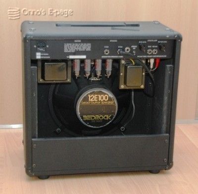
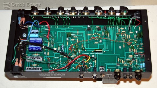
First I took the amplifier from its cabinet and started to check
continuity on the output transformer, which was fine.
Then I checked the power transformer, whose secondaries
were fine, too.
All the connections to the primary were not directly
accessible for measurements.
I measured at the mains input receptable.
No continuity in either position of the mains switch.
After checking the mains fuse I pulled the faston connectors from
the mains switch, which have plastic isolating sleeves
covering them and kept me from measuring the primary windings.
Oddly, these were both ok.
I put the connectors back in place and checked on the
mains receptacle. Now I had continuity.
I hooked up the speaker and inserted a mains cord.
I switched on the amp and monitored the voltage on the
HV electrolytics.
It went up to 410 V and back to 390 as the valves
came up.
Some noise was coming from the speaker.
I did several checks to see the amp really worked.
Only, it squeeked at some settings of the controls.
I wanted to investigate that.
It turned out to be some 6.2kHz oscillation, apparently
coming from the pre-amplifiers.
Finding a circuit diagram wasn't easy, there only is a
low-res scan to be found on
The Bedrock Amplifier Tribute Page,
along with some hand-drawn schematics,
I wanted to find out if the oscillation
originated from the pre-amps themselves or was
caused by feedback from the output stage.
That is plausible, as the anode leads of the
output transformer are running quite closely to the pre-amps.
I unsoldered one side of the coupling capacitor (C18) that links
the pre-amps to the phase splitter.
Then I plugged the load resistor back in and inserted a
signal in the output amp. This worked as it should.
I switched off and connected my signal generator to the input
and my scope to the output of the pre-amp.
Now I saw the oscillation again, although the output amp
wasn't connected and could not cause any feedback.
So I knew the pre-amp was oscillating of itself.
Alas, looking for the cause, I made
a little mistake
that caused me some extra work.
Fortunately, all ended well.
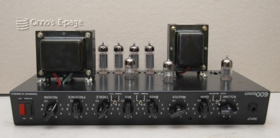
Besides the two 12AX7WB pre-amp valves, the Bedrock 600
uses semiconductor circuits in the pre-amplifier.
It has two dual opamps, one for the reverb unit and
one for the effects loop input and output.
I decided it would be more relaxed to test
these low voltage amplifiers first,
without the high voltage supply.
I connected external + and - 18V supplies.
Immediately, the 6.2 kHz signal was back.
It came from the reverb tank driving amplifier.
It has a power stage
consisting of a TIP29/TIP30 complementary power transistor pair
driven by one half of a TL072P opamp.
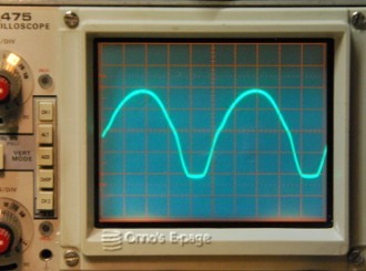
This amplifier was oscillating, the output signal went from
rail to rail, 30Vtt.
I wanted to make sure the oscillation wasn't caused by
the absence of the reverb tank and connected the reverb
tank to the amp.
The frequency changed to 25 kHz but it remained
equally strong. This was really nasty: at 25 kHz it would
be inaudible but it would disturb the amplifier operation
and it
might cause a
flashover
if the loudspeaker wasn't connected.
Though I wasn't 100% sure from the low-res schematic,
I thought that the feed-back resistor should be 9.1 kΩ.
The amplifier had an 18k resistor, though.
I soldered a resistor in parallel, and the oscillation was gone.
The driver amp was quiet now, both with and without the reverb tank.
I didn't really worry about the lower driving signal into
the reverb tank,
as my friend had told me he wasn't using the reverb anyway.
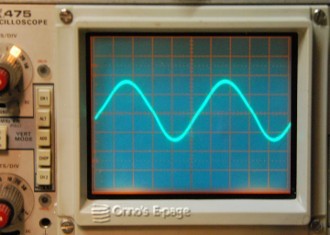
I inserted the valves and tested the amp.
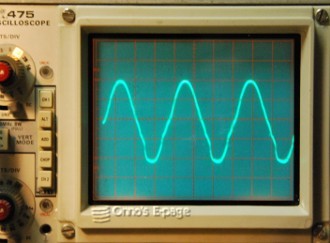
Now it was working fine. No oscillation.
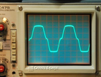
A straight sine at 1 kHz and 30W, becoming more
like a square wave
at overload conditions, as push-pull amplifiers do.
I tried some additional research on this Bedrock amplifier
and its reverb amplifier.
I found only one reference on a discussion panel,
from someone citing exactly the same oscillation problem
in the reverb driver amp.
Although this wasn't actually causing the fault,
I think that from a standpoint of amplifier
stability, the reverb control is placed in an unfortunate place.
It is at the far right of the control panel, while the reverb preamp
is all the way at the left.
This means a long low-signal trace traveling along the PCB.
But it has a low impedance, which probably saves the situation.
I find this even more surprising because the amp is using
four analogue switches (LED-LDR sets) in other places in the preamp,
which is a bit expensive but allows the designer to
prevent hum, noise and instability.
Why not use such a LED-LDR set as a reverb control?
So the amp is working now but the fault isn't 100% certain.
Maybe the oscillation was squelching the output amp.
But why did the repairman say the power transformer was bad?
Maybe the stand-by switch was dirty.
Maybe the fuse hadn't been placed correctly.
Anyway, the amplifier kept working fine during the months after.
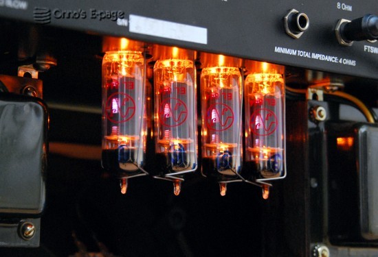
I made some photographs showing the glowing
output valves.
Through a hole in the anodes you can see the characteristic blue
haze in the output valves.
I noticed on this picture that the second valve
in the row is showing some more red light than the
others.
I suspected the
output valves might not be matched correctly.
This valve might draw more
grid current than the other ones.
So the next day I set up a test circuit and measured the
chracteristics of all four output valves.
They were very close.
The valve that looked a bit more red was actually
the one drawing least screen grid current.
So there was nothing wrong with it.
After this, the owner made a soundcheck and was happily surprised.
Good.

Transformer specs
One month after posting the first version of this page,
someone contacted me to ask if I had the transformer
specifications.
From my notes I could make a fair guess, but I
decided it would be better to borrow the amp and
make some decent measurements. Which my friend fuond ok.
By the way, if this information is helpful to you,
please let me know through the
feedback page.
| Output transformer |
type MMC-11629 |
|---|
| Core: |
95x80x32mm (EI95, 32 mm stack) |
| Primary: |
Raa=3.6-4kΩ(?), DC resistance 92Ω |
| Secondary: |
Gnd - 4Ω - 8 Ω, DC resistance 0,3 + 0,2 Ω |
The primary impedance has been determined by multiplying the
secondary impedance times squared voltage ratio at 50 Hz, giving 3.6k.
I also measured the current drawn by the primary connected to
230V AC with an 8 Ω
resistor connected to the secondary, giving 3.8k.
The result surprises me a bit.
For an output stage with 4 EL84's normally a primary impedance of 4k is specified.
I expected it to be higher because of the high plate voltage.
My results of 3.6-3.8 kΩ may be erroneous, but I don't see how.
I would use a 4k P-P transformer rated for 50W
if I needed a replacement.
| Power transformer |
type MMC-11628 |
|---|
| Core: |
105x88x44mm (EI105, 44 mm stack) |
| Primary: |
115+115V, DC resistance 6.5Ω |
| Secondary 1: HV |
600V 250mA ct, DC resistance 65.5 Ω |
| Secondary 2: LV/bias |
32V 250mA ct, DC resistance 3.8 Ω |
| Secondary 3: heaters |
6.3V 4A, DC resistance <0.1 Ω |
The voltages have been measured at a moderate load, not at full power.
The rated currents for the HV and LV/bias secondaries have been
estimated.
By the fact that the ratio of DC resistance to secondary voltage
of these two windings are roughly equal, it can be determined
that they have the same wire size thus same rated current.
When replacing the power transformer, keep in mind that the neon
pilot light is connected to one half of the split primary.
When a transformer with a single primary is used,
an extra resistor has to be put in series with the pilot light.
Which output valves
This amp
is not suitable for just any EL84 brand.
It needs a ruggedized variety. According to my friend,
originally it had Sovtek valves.
The JJ brand valves his former guitar repairman
had inserted, were working ok.
Personally, I would use type 7189.
These are military grade versions of the EL84/6BQ5
and they are specified for 400V operation.
Even better, the 7189-A is specified for 13.2 W
plate dissipation as opposed to 12 W for
a regular EL84.
So it should be better suited
for an amp like this.
Extended testing
As mentioned previously, my friend already had bought a new
amp and wasn't using the Bedrock any more.
In the meantime, my son had bought a guitar and I
hadn't yet finished the
amp I was building for him.
So in the second half of 2014, I borrowed the Bedrock
and my son used it for his first guitar experience.
The amplifier kept working fine and gives a
warm rock&roll sound.
The reverb unit gives a nice extra to the sound.
The amp went back to its owner after this
and my son went on using
his own amp.
and the Geloso G215AN.