Guitar combo flashover
Now I know perfectly well that one should NEVER operate
a valve amplifier without a load (speaker or load resistor)
connected.
The inductance of the output transformer when not loaded
will cause high peak voltages that may damage your transformer,
your valves or other parts.
I never intended to even experiment with this condition,
as I expected immediate damage without much to see.
What happened could be called spectacular...
One moment you are feel on top of the worls to have reanimated a guitar
amp that the “expert” had declared dead.
The next moment you fry it.
This does get one's self-confidence down again.
I was fixing a friend's Bedrock 600
and found it had an irritating tendency to oscillate.
The oscillation was coming from the pre-amp.
When only the clean channel was used, it was just an
irritating squeek of 6-6.5 kHz.
When adding more amplification using the effects loop
or distorted channel, the amp would really go crazy.
After some tests, I wanted to find out if the oscillation
originated from the pre-amps themselves or if it was
caused by spurious feedback from the output stage.
That is plausible, as the anode leads of the
output transformer are running quite closely to the pre-amps.
I unsoldered one side of the coupling capacitor C18 that links
the pre-amps to the phase splitter.
Then I plugged the load resistor back in and inserted a
signal in the output amp. This worked as it should.
I switched off and connected my signal generator to the input
and my scope to the output of the pre-amp.
Now I saw the oscillation again, although the output amp
wasn't connected and could not cause any feedback.
So I knew the pre-amp was doing this all by itself.
I wanted to see if the oscillation would change if the
pre-amp was loaded by the output amp again.
So I pushed the coupling capacitor back in place and watched
my scope screen to see what happened.
The results were quite unexpected.
I hadn't noticed I had forgotten to plug in the load
resistor after the last change of the test leads.
Immediately, a flash-over occurred somewhere near the 4 &Omega
output jack and a fire started.
It took me several seconds to gather my wits and throw
the switch on my test bench.
The fire stopped and black snow drifted down slowly.
These were flakes of soot from the PCB or
the plastic of the output plug near the flashover.
I threw open the window, checked whether the fire was
really out, and went away to recover from this unpleasant surprise.
The next day, I mopped up the soot from the room and checked
the amplifier.
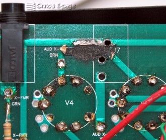
After I cleaned the black stuff from the PCB and the
connector, I saw why the flash-over had occurred at
this specific spot. Here one of the anode connections runs
very close to a ground track.
This was the shortest path for the high voltage to take.
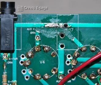
Right after that, the heat from the spark had charred
the epoxy plastic of the PCB, the carbon forming a current path.
This would sustain the flash-over until the power was
cut.
I checked the output transformer and was happy to see
it was not interrupted.
I had to remove the PCB from the chassis to get to the
solder side and unsolder the output jack.
First, I numbered and extracted the valves.
Then I had to remove the knobs and nuts of the effects
controls and all the jacks on the back.
In order to get some manoeuvering space, I also had to
unscrew the mains receptacle.
Finally, I had to unsolder the output amp ground wires,
the heater voltage wires from the power transformer and
all the wires from the output transformer.
Boy, this lapse of attention was causing me a lot
of extra chores.
I first cleaned the inside of the chassis and the
parts of the PCB I could reach.
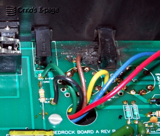
Then I unsoldered the 8 Ω output jack and
cleaned the PCB under it.
The PCB was badly charred.
The anode track had partly been burned away.
I wondered why the designer of this PCB had taken the
risk of letting HV tracks run so close to ground tracks.
Under the 8 Ω output jack the distance of the
anode track to one of the solder pads for the output jack
could not have been much more than 1 mm.
I grinded away the charred epoxy and coated the
exposed PCB and tracks with a protective isolating
plastic spray.
After this, the PCB looked healthier.
Searching for this particular type of
Jalco 6.35 mm jacks, I found these were
hard to get.
The jack didn't look burned, the plastic was a just
a bit warped and covered with soot
so I cleaned it using detergent, white spirit and alcohol.
I soldered a wire between the two anode
connections of the valve socket to replace the
PCB trace that had been burned away and
reinforced the ground track involved in the flashover.
Then I resoldered the jack.
This looked better.
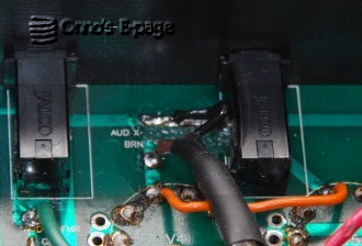
While I was at it, I decided to put a shielding mesh
around both the anode leads of the output transformer
to reduce spurious feedback from the HV signal on
these wires.
The screen was connected to the ground track.
I slid an insulating sleeve over the screen to prevent short-circuits.
I also considered adding screen-grid resistors to
make life easier on the output valves, but decided not to.
I soldered all wires back in place and screwed the
nuts and knobs back.