Philips GM2883/03 RF generator

The Philips GM2883/03 is an RF signal generator from 1954.
This specimen I acquired in March 2006 is looking excellent
and I trust it will be a useful tool.
The GM2883 is an RF generator covering frequencies from 100 kHz to 30 Mhz. It has a special 400 -500 kHz range for the precise aligment of the IF stages of an AM radio. The original GM2883 model dates from 1949. The GM2883/03 is the third improved version, issued in 1954. In that year, the EF50 HF penthode may have been a bit obsolete and expensive, but still a very good option to build a rock-stable HF generator.

Chassis seen from behind.
Valves from left to right:
OB2 ECC81 EZ80 and 3x EF41.
I bought this signal generator through Internet from a hobbyist, who did not know if it was functional or not. It was in good condition, so I was confident I could get it to work again. The hammered metal finish case does not have any rust and the anodised aluminium face plate is in excellent shape. The leather handle on top is still strong and supple, not dried out.
I took the chassis out of the case. Everything looked fine. The valves didn't have any visible signs of wear. I peeked into the oscillator compartment to see the range switch, which is a set of coils on a carrousel just like the GM2882 has. The range switch was clean and looking good. Then I tested the power supply electrolytics. They hardly had any leakage current and did not need reforming.
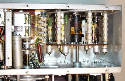
A peek inside the range switch compartment, from the bottom.
The only thing that I didn't like, was that the glass of the output meter was loose and seemed to block the meter's movement. A few weeks later when I used the generator to align the Eddystone 840A receiver, I noticed on my scope that the modulation of the signal was very weak. Not 30%, as it should be, but hardly 5%. And although the generator was stable, the output frequency was always higher than the pointer indicated. Finally I noticed that the pointer on the frequency dial turned in the opposite direction to the movement of the frequency control knob. This is not grave, just awkward.

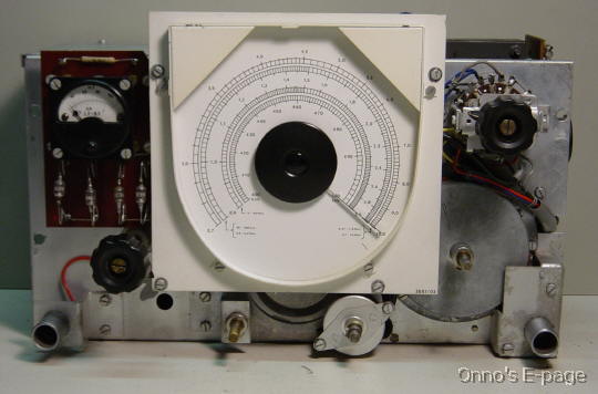
Front removed, dial and meter detached
Then I started to fix the meter. I had to unmount the meter from the front and partly disassemble it to get to the loose glass. I cemented the glass back in place. Then I checked the meter which had a 100 μA sensitivity as specified. After I put the meter back in place, I turned on the generator. The meter reading was still too low. I checked the rectifier (four very early germanium diodes, type OA51) using a LF generator with 1 V output, as specified in the service manual. The meter reading was fine, so the diodes and the meter were OK.
I realised that the output meter first rectifies the output signal, and then measures the resulting LF signal. The manual specifically states that the meter reading depends on the RF output signal and the modulation depth. Since the modulation depth was too low, I should take a look at the modulator. I first checked the output of the LF oscillator. It can produce two different frequencies. At 400 Hz it gave 30 Vtt output, at 2500 Hz it produced 100 Vtt, resulting in 3V and 6V on the input of the modulator stage, respectively.
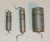
These used to be high quality capacitors.
They're leaky nonetheless.
Now I wanted to know why the output signal was too weak on the 400 Hz setting of the LF oscillator. Well, the LF oscillator also had these "quality" paper capacitors, which were now very much under suspicion. Not only was the output voltage too low, the output frequencies were also off. I measured 334 Hz and 2050 Hz. So I replaced the capacitors that determine the output frequency. Now the output was stronger and back to 400 and 2500 Hz. After some fiddling, the meter reading was just right.
Generator chassis reassembled and almost finished.
Now the generator works fine, and it is a real asset for my hobby lab.
Copyright © 2006 by Onno's E-page published 2006-04-02, last updated 2006-10-18