Philips B5X74A radio (1957)
The Philips B5X74A is a beautiful upper mid-range radio from 1957.
It has AM and FM reception and it boasts a
transformerless output stage for excellently good sound.
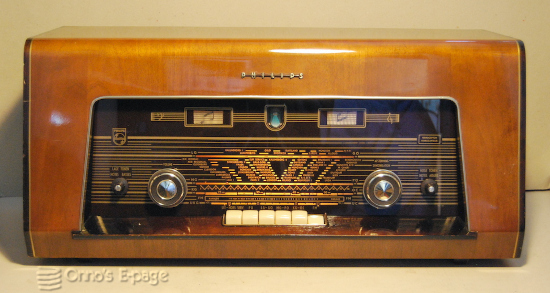
For comparison: a B5X62A I owned in 2008.
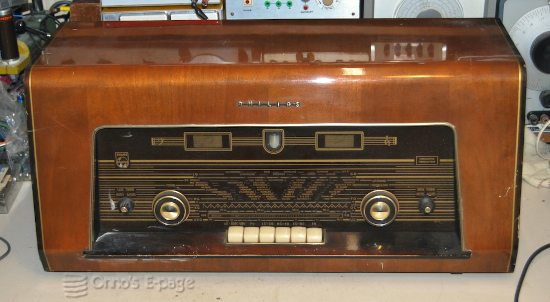
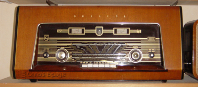
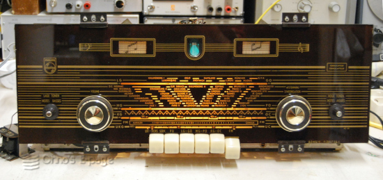
The B5X74A as I received it, scratched and dirty.
Then I connected it to my variable transsformer and turned up the voltage slowly. No sound. I connected an AF generator to the record player input and got sound. The voltages in the output stage and on the AF pre-amplifier were ok, relatively to the supply voltage that was a bit low. The voltages in the MF stages were confusing.
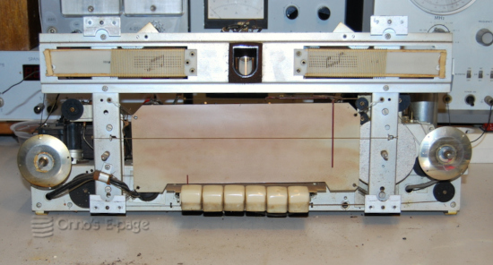
Chassis out of the cabinet.
Now I knew I had to take out the chassis and do a proper repair. I had to remove one of the speakers to make room to let the the tuning dial pass. Inside the cabinet, a strip of wood had come loose that held the wiring to the speakers and two metal clamps that should keep the upper part of the frame holding the dial glass firmly to the front of the cabinet. After removing the chassis I hung it in my service brackets.
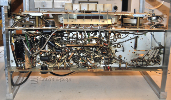
View from under the chassis.
Measurements showed that the EF89 was weak. Replacing it and the EZ80 rectifier improved reception a bit. After cleaning the FM section of the band switch, FM reception was working, too. The sound was good and mostly undistorted, but going through the band there was a weak secondary response on every station, meaning the detector and IF had to be realigned.
I decided to align the AM circuits first. This was a bit risky. This radio has a type of IF transformers that have a small brass alignment screw on top. Inside, a small ferrite core is attached to the screw by a plastic tube. These cores are notorious for falling off the screws, making any alignment impossible. But I had no trouble.
Then it was time to align the FM IF transformers. This is also risky, as they often have stuck cores. If you apply too much force while trying to turn the core, the coils may come loose and turn with the core, resulting in broken wires. To soften the wax, one can warm the cores or use some kind of solvent. Using eardrops, waiting half a day and carefully wiggling the cores to and fro, gradually increasing the movement, I was able to free them. I then connected my RF generator and aligned the FM IF transformers. I concluded by aligning the secondary of the ratio detector again. That was funny: turning the secondary core results in an odd cracking sound. As a result, FM reception was improved.
The mains switch had remained stuck in the “on” position during all this. After opening and lubricating, it worked again. I replaced the small felt patches that had come from between the bandwidth switch keys while cleaning them. These prevent the keys from scraping against each other and provide for an even spacing of the keys.
Chassis after repairs working again.
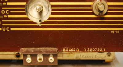
It's a B5X74A but it says B5X62A on the scale.
Then I thoroughly cleaned the cabinet and polished it. I filled a few deep scratches with shellack. I cleaned the speaker grills. I glued the wooden strip that had detached and left the glue to set for a night. I attached new foam strips around the opening where the dial glass sits. Then I reinserted the chassis and the speaker and reconnected the speakers. I screwed the two clamps that keep the upper rim of the dial glass to the cabinet and found out what the two 1.5cm large cubes of felt were for, that had initially been lying on the bottom of the cabinet: they were to be pinched between these two clamps and the metal supports of the dial glass.
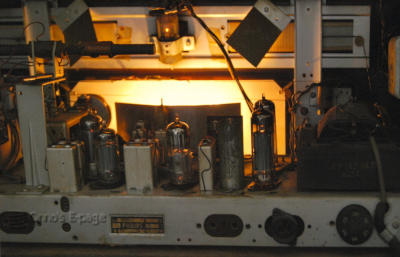
Beautiful atmosphere with glowing valves.
Copyright © 2026 by Onno's E-page published 2026-04-11