Philips GM2315 R.C. generator (1950)
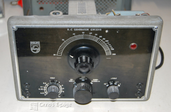
This is an LF generator producing sinewaves from 20 Hz to 20 kHz.
I bought it from a collector in 2015 to have a spare LF generator.
It landed on a shelf, but in 2026 I found it back and restored it.
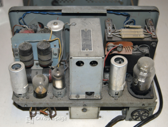
A view at the inside from the back.
The valve line-up of the GM2315 is:
| EF41 | pentode as pre-amplifier, |
| EF41 | pentode as second amplifier stage, |
| EL41 | power pentode as output stage, |
| AZ2 | rectifier. |
| 220V 7W | incandescent lamp as regulator |
The model pre-dates the GM2317 by three years but the circuitry is very similar. It is a Wien-bridge RC-generator with an incandescent lamp in the negative feedback loop of a three-stage amplifier acting as a stabilising component for the loop gain. The GM2315 is simpler than its successor. To start, it is smaller, it does not have an output meter and the the frequency control knob is sitting directly on the shaft of the tuning instead of using a string-drive. It has no choke in the power supply but only a resistor. The incandescent lamp is a single 220V type, whereas the GM2317 has four smaller lamps in series. By the way, you cannot see the lamp glow, not even with an infrared camera.
In early 2026, after fixing the GM2317 RF generator, I decided to take up the GM2315. I started the obvious repairs. I fixed two broken supports for the power supply resistors by glueing them with epoxy cement.
I checked the coupling capacitor C13 and found it was a bit too leaky. So I replaced it with a 0.47μF polyester capacitor. I left the other large paper capacitors as they were, as they do not impair the generator too much. I reformed and checked all electrolytic capacitors. They were not leaking too much so I kept them as well.
The generator was powered on and started to work. Checking the voltages it turned out that the power supply voltage was good. No problems here. I did have to clean the contacts of the output attenuator switch. Then I had a good working LF generator.
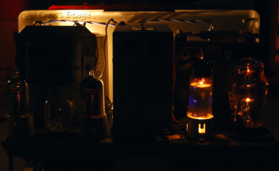
The GM2315 showing the glow of the valves. No light from the regulator lamp.
Copyright © 2026 by Onno's E-page published 2026-03-08