Brown QUAD FM4 tuner
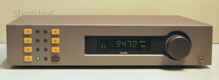
In 2018 I bought two of these tuners from an Internet auction site, one with yellow buttons and one with grey buttons. From their photographs it was obvious that both were defective. They turned out to have had a leaking memory backup battery, damaging the circuit boards and some components. Repair was succesful for both of them.
After I had brought the first FM4 back to life, I started with the second one. This one has a “brown” color scheme: brownish grey cabinet, brown tuning knob and yellow pushbuttons. I assume this color scheme carries the reminiscence of the seventies, while the “grey” version fits better in the eighties. The serial number is slightly over 10000.
Like the first FM4, this tuner didn’t respond to the pushbuttons at all. The tuning frequency was stuck at 87.25 MHz and it had two of the indicator LEDs lit, where only one should be.
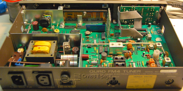
When I slid the chassis out of the cabinet, it became apparent that the NiCd battery had leaked its chemicals over the circuit board, attacking the protective coating, the copper tracks and the leads of some of the components. This tuner had probably been on a shelf for decades, never recharging the memory backup battery. The microcontroller didn’t have a clock signal. From the experience with the first FM4, this would be due to stray currents disturbing the CMOS oscillator circuit of the TMS1000 microcontroller.
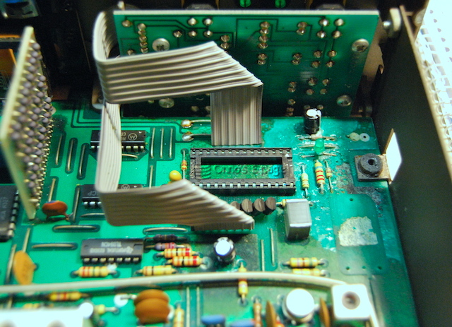
I had to replace a number of components. The leads of the two diodes and the 1N823 zener were corroded and they broke when I touched them. Two resistances were bad. The green LED on the circuit board was interrupted. First I removed the battery and unsoldered the microcontroller socket. The reset capacitor C10 fell apart when I unsoldered it. Two electrolytics measured faulty after removal. I chiseled away the most damaged areas of coating from the circuit board on both sides, and polished the copper surface using a fiberglass brush. I cleaned the board using cotton buds with vinegar and then clean water and alcohol.
After the components had been replaced and the exposed copper coated with plastic varnish, I tried the tuner. It did start up and respond to the pushbuttons. But it wasn’t working well.
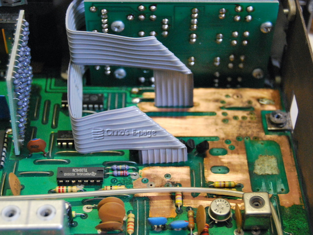
I tried tuning it up and down and back again. Maybe I was a bit too rough. Suddenly the tuning knob blocked and when I used a bit of force, something made a grinding noise. This wasn’t good. The frequency drifted away. The tuner was drifting all over the place. Checking the tuning pot revealed that it was broken.
It turned out to be hard to find a suitable replacement. All the available 10-turn pots have a 20 mm long shaft, while Quad had used one about 40 mm long. Finally, I ordered the one available and decided to use some kind of extension shaft. This was easier said than done. The vintage extension shafts in the junkbox were too coarse and too long. The connecting cylinder alone was longer than 20 mm already. I shortened one of the connecting cylinders, sawed off the shaft of the original pot and cemented this in the connecting cylinder. Then I was able to screw the extension shaft to the pot.
After this, I mounted the replacement pot and added the extension shaft. I enlarged the hole in the front glass (acrylic, actually) so the connecting cylinder would fit through the hole.
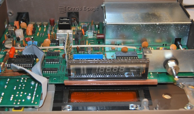
The tuner was working now. It would start in manual tuning mode. At first, the highest frequency it would reach was around 104 MHz. After warming up, it went up to about 108 MHz. This was odd. The master tuning voltage after the CMOS switches and opamp varied from the −reference voltage to 8.33 V, which equals the +reference voltage. Though the tuning voltage was stable, the tuning frequency wasn’t.
The actual tuning voltage applied to the varicap diode of the tuning oscillator is derived from the master tuning voltage by a fixed voltage divider of 33k and 68k and decoupled by C9, a Tantalium electrolytic capacitor, then fed to the varicap through a small inductor. The varicaps of the three rf tuning circuits get their tuning voltages through a trimpot, allowing for alignment of all four tuned circuits.
It turned out that the voltage on C9 was drifting, despite the tuning voltage being stable. Right after switching on, the voltage on C9 was only 5.5 V. After 15 minutes or so, it would rise to about 6.3 V. Also, I noticed that just after switching on, the tuner was quite insensitive, but after warming up the signal indicator reading was higher. In hindsight, this meant that the oscillator and the preselection RF tuning circuits were out of alignment.
I suspected the tantalium capacitor and replaced it. This seemed to work at first, but the next day the problems reappeared. I wondered if my replacement capacitor was bad, and replaced it by a 2.2 μF polyether cap. This seemed to work, although the tuner still wasn’t very stable. The next day, drifting problems were as bad as before. During measurement I noticed that even the load from my DVM (10 MΩ) would cause the tuning frequency to change about 0.05 MHz, the smallest increment the built-in counter shows. This corresponds to a change in tuning voltage of about 10 mV. So it appeared that even a very small leakage current already influenced the tuning significantly.
Disconnecting the small choke coil from C9 to the tuning circuit, a current of a few μA could be measured to be drawn from the tuning voltage. Unsoldering the varicap diode and testing it using an external power supply revealed that the varicap diode itself was leaky. Now how to replace this BB204 double varicap diode? How long would it take to order? Against all odds, I found 3 “B204G” semiconductors in my to-be-sorted box of salvaged semiconductors. These looked like transistors in TO92 case but measured like double diodes. I soldered one in… and it worked. Only, now the tuning frequency was 112 MHz. Maybe because I used BB204G instead of BB204B, having a slightly different characteristic.
Adjusting the oscillator coil was all that was needed. This resulted in a tuning range of 87.2 to 108.2 MHz. The oscillator frequency remained stable now and the preset frequencies were repeatable. This is important because the microcontroller stores the tuning voltage, not the actual frequency. Adjusting the preselection tuned circuits did not make a difference, so apparently this varicap was compatible with the other ones.
I drilled a hole in the circuit board to mount a CR2032 battery holder, removed the charging resistor R12 and clicked a lithium battery in the holder. As with the other FM4, this was sufficient for the internal RAM of the microcontroller to hold its contents while the unit is powered off.
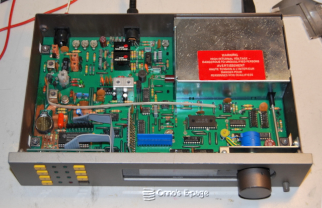
I have been using this tuner to provide music in my shack for some time. It kept on working fine and never had any memory loss. But after a few years I decided to trade it to make room.

Copyright © 2022-2026 by Onno's E-page published 2026-08-26 last edited 2026-09-04