Grey QUAD FM4 tuner
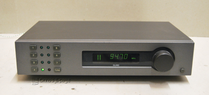
In 2018 I bought two Quad FM4 tuners from an Internet auction site, a brown one and a grey one. They were sold as defective, not responding to the controls. I was able to fix them both.
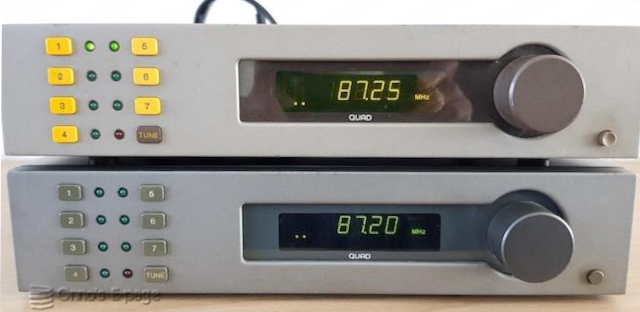
In 2018 I was looking for a QUAD tuner to match the QUAD 34 and QUAD 405 set I had just bought. On an Internet auction site I found this advert offering two defective QUAD FM4 tuners, with different color schemes. The first one had grey buttons and a grey case. The second one had yellow pushbuttons and was slightly brownish in color. It seemed a bit older.
The tuners came out of the inventory of a closed down hi-fi shop. The seller wrote they were not functional. This was even visible on the photographs: the LEDs indicating which preset was active were disbehaving. The upper tuner had two LEDs lit, the lower none. And both displayed a frequency slightly under the FM band. When the tuners arrived, neither responded to the pushbuttons and they could not be tuned. The frequency was stuck at the low end of the FM band. I immediately thought the grey one would make a nice combination with my QUAD 34 and started to work on it. After some web searching, I found that a dead memory backup battery is quite common for this type of tuner. Also, there was a mention of microcontrollers failing. If so, a replacement would be hard to find, I dreaded.
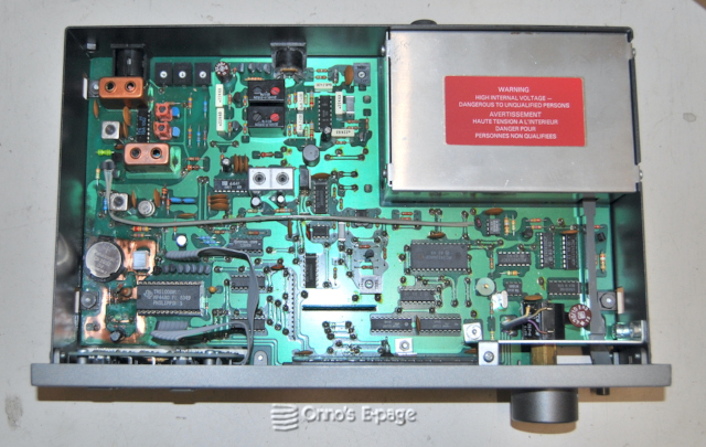
Opening the case of the grey one, I was unpleasantly surprised by the looks of the built-in NiCd battery. It was not only dead, it had been leaking corrosive chemicals over the circuit board, attacking the protective coating on the circuit board and corroding the copper tracks and the wires of some of the components. Measuring the microcontroller clock signal and other signals showed no activity. I pulled the microcontroller from its socket and started to clean the circuit board.
The chemicals from an NiCd battery are alkaline, so I applied some acetic acid (household vinegar) with a cotton bud to neutralise the stuff. After this I cleaned the circuit board with clean water and alcohol. The tuner still wouldn’t work. The display was stuck at 82.10 MHz.
I checked the supply voltage. This wasn’t ok, it had a 0.5V asymmetric ripple. So I checked the bridge rectifier, which turned out te be defective. After replacement the 12V supply voltage was ok, and the display read 87.20 MHz.
Still, the microcontroller wasn’t working. I borrowed the microcontroller from the brown FM4, but that didn’t work either.
I collected the schematics and started to read them carefully. After analyzing the circuitry around the microcontroller I set up a test bed containing the most essential circuits to test the microcontroller. It consisted of the reset circuitry and the clock oscillator components (an 180 pF capacitance and a 15 kΩ resistance connected to pins 25 and 26). I connected my scope to it and watched.
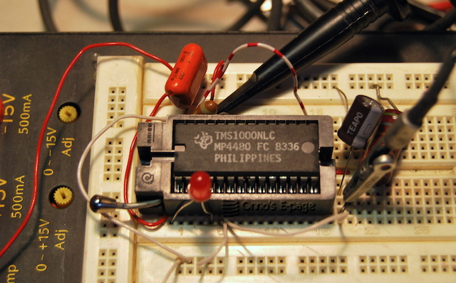
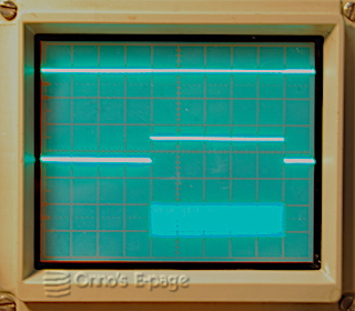
Now the TMS1000 controller came to life. It was turning on and off its clock oscillator every 10 ms. When I touched pin 27 with my channel-B probe, the clock suddenly ran continuously. In the QUAD circuit diagram, there is a connection between pins 15 and 27. After adding this connection on the breadboard, the microcontroller kept running. Also the “keyboard” scanning signals could be observed on pins 6 to 9. Both microcontrollers behaved identically. I was happy to have two of them to compare them. They seemed to be OK but they didn’t function in the tuner itself. They were very sensitive to even the smallest input signals, for they reacted even to the touch of a scope probe. As this is a CMOS version of the TMS1000, this sensitivity is plausible. I assumed that stray currents caused by the leaked chemicals on the circuit board may have been the cause why the microcontroller’s clock didn’t work.
I thoroughly cleaned the circuit board and replaced all suspicious components. I unsoldered the IC socket, which had some greenish pins. I chiseled away the coating and copper oxide from the damaged areas of the circuit board on both sides, and polished the copper using a fiberglass brush. I cleaned the board again using cotton buds with vinegar and then clean water and alcohol. I sealed the exposed copper traces using a protective plastic varnish. I soldered a clean new IC socket. Checked the green LED D23, which was defective. Also replaced diodes D21 and D22 and R12.
Not yet inserting the controller, I turned on the tuner and checked the voltages on the pins of its socket. This looked ok. I inserted two pieces of wire to make IC 5 switch the tuning voltage (point G) to the tuning pot, a 10-turn potmeter. Hooray! The pot would tune!
I turned off the tuner and inserted the microcontroller. Switched it on and immediately the red “manual tuning” light lit. I could store a station under one of the pre-set buttons, go back to manual and reactivate the preset. Of course, the tuner would loose its memory when switched off.
In order to prevent future damage, I decided to replace the NiCd battery with a standard 3 V non-rechargeable lithium battery. These last for 10 years on your computer’s motherboard and usually don’t leak. Drilled an extra hole in the circuit board, soldered a battery holder on the board, removed the charging resistor R12 and clicked a type CR2032 lithium battery in the holder. This proved sufficient for the internal RAM of the microcontroller to hold its contents when the tuner is powered off. I don’t know how long it will last, but it has for over eight years now.
This fine specimen of British design has found a place in my living room and I have been using it for regular listening for years. It has kept on working fine since. Alas, the local cable company has stopped the analogue FM broadcasts so I had to replace the tuner by an Internet radio. The tuner has moved to my work room.

Copyright © 2022-2026 by Onno's E-page published 2026-08-26 last edited 2026-09-04